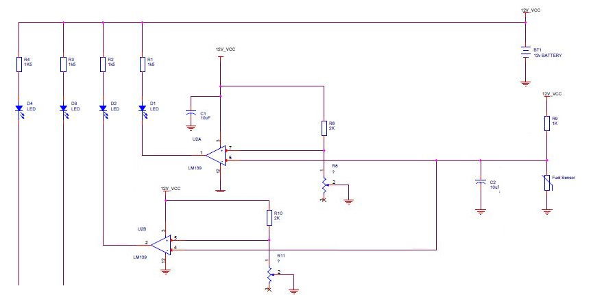
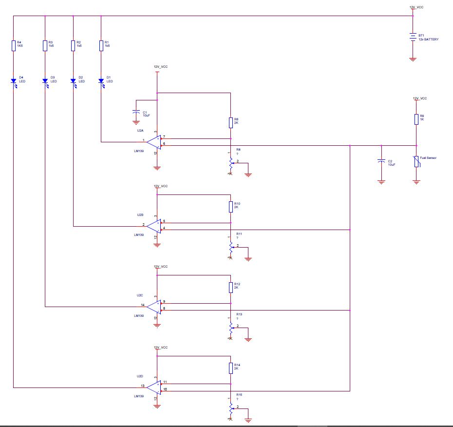
Circuit diagram for calibration of fuel tank sensor

Make your own tank gauge calibration module.
A simple voltage comparator circuit for non-linear fuel tank shapes.
There are 4 LEDs and 4 independent voltage comparator (within a common chip) and a single fuel sender unit.
Each voltage comparator has an input from the sender unit and a trimmer potentiometer. The output of each voltage comparator is an LED.
How it works
The fuel sender will send a voltage ranging from 0v to 5 volts depending on the float position to the - pin of each voltage comparator.
The trimmer pot allows the output control of the LED to be set.
The comparator simply compares the voltage between - and + pins and will set the output accordingly.
If voltage on + pin is higher than that of - pin output is OFF, if the voltage on + pin is lower than that of - pin output is ON

Parts List:
4 x 1K5 resistors
1 x 1K resistor
4 x 2K resistors
2 x 10uf capacitors
4 x 10K potentiometers
1 x LM139 Quad Differential Comparator