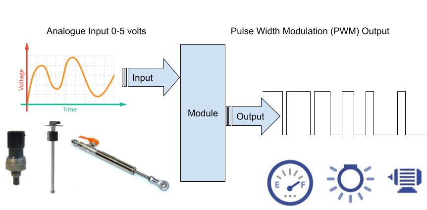
Analogue input to PWM Output

A fully calibratable electronic module which will convert an analogue input signal to a Pulse Width Modulation (PWM) output.
Analogue signal converted to PWM power
- Low power signal to control higher power devices.
Calibration mapping of input signal to output duty cycle.
- Input range is 0 – 5 volt can be mapped to numerous PWM outputs.
- Linear sensors mapped to linear or complex non-linear outputs
- Mapping allows sensor to device inversion
How the module works – Input
The module input operating range is 0 to 5 volts analogue.
This input range is then converted to a digital value by dividing the range 0-5 into one of 1024 values.
Each digital valve is to equal 0.0049 of a volt or 4.9mV.
Input analogue to digital conversation:
Analog to Digital Converter (ADC)
10 – bit ADC
210 = 1024 (range = 0 - 1023 as zero is counted as a value)
Input resolution is 5 / 1024 = 0.0049
So
Digital valve 0 = 0V
Digital valve 1 = 4.9mV
Digital valve 2 = 9.8mV
-
-
-
Digital valve 1023 = 5 V
The ADC converts the analogue input voltage to a highly accurate digital value which can be used with the programming of the module code.
How the module works – Output
The output is a Pulse Width Modulation (PWM).
A PWM is a power circuit which is switched on and off extremely fast.
The amount of time the circuit is switch ‘ON’ and ‘Off’ can be varied, this is called the duty cycle.
If the output PWM duty cycle is 5 % , then the circuit will be On for 5% and off for 95% - Low power.
If the output PWM duty cycle is 95 % , then the circuit will be On for 95% and off for 5% - Hi power.
The PWM output can be set at any value between 0% - 95%.
This gives a high level of adjustment.
How the module works – Calibration
Mapping allows the input signal digital valves to be mapped to an output duty cycle percentage.
This mapping is done in C programming language but only a very low level of programming knowledge is required.
For example:
If input digital valve is between the range of 250 – 350 set PWM to 45%
Note:
The number of mapped points is variable depending on how much accuracy is required.
There are effectively 1022 input valves so each one of these could in theory have itself own output duty cycle.
Each of these operational instructions is independent allowing non linear output to liner input relationships to be established.
For example:
Input digital value 250 – 350 set PWM to 45%
Input digital value 351 – 450 set PWM to 5%
Input digital value 451 –550 set PWM to 25%